


Schleith GmbH and PASCHAL, the proven combination for sluice refurbishments
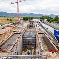
For the ongoing sluice refurbishment in Schwabenheim, the Schleith GmbH is using PASCHAL. After the success with the sluice refurbishment in Lauffen four years ago, the contractor comes back to our formwork and scaffolding systems.Following the precise specifications and ideas of the customer, the Heidelberg New Waterways Construction Authority, the complete renovation of the left lock chamber required a large number of components and construction methods, including the planar concrete repair of the two chamber walls, which must not have any penetrations, which meant single-sided formwork was used. Schleith GmbH was commissioned on 1 April 2020.
Schleith GmbH needed only 565 m² of LOGO.3 wall formwork, 45 t of GASS aluminium shoring system and 45 t of PASCHAL TG60 scaffolding as rented equipment to refurbish the approximately 2,400 m² of reinforced concrete lock walls.
PASCHAL has been involved since the end of 2019, and initially supported Schleith GmbH with formwork and scaffolding proposals, in order to implement the technical specifications of the building contractor and develop a cost-effective rental offer for the construction company. AutoCAD with PASCHAL-Plan pro was used for the differentiated formwork planning and RSTAB from Dlubal for the static modelling and calculation of the support.
Preliminary work on the lock chamber
Before the chamber walls received a new concrete shell, the existing chamber walls and the niches for access ladders and bollards were first milled off. A haunch on the chamber floor was then removed to allow refurbishment of the existing ASR damage to the concrete.
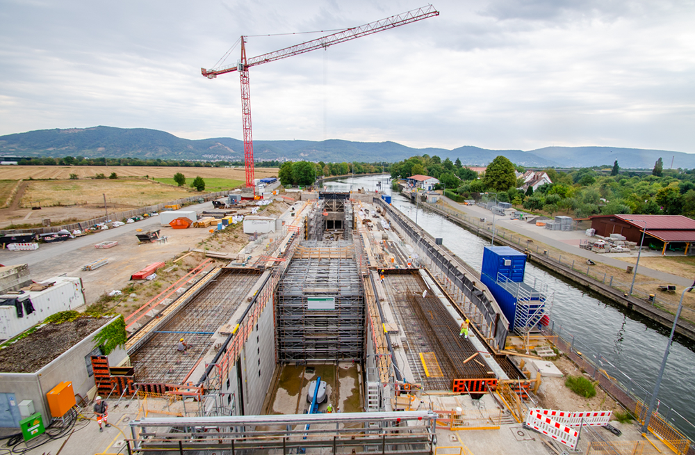
Schleith GmbH used LOGO.3 wall formwork, the GASS aluminium shoring system and PASCHAL TG60 scaffolding as rental equipment for refurbishing the sluice during ongoing operations.
Additional anchoring of the lock floor and walls
Static strengthening was required for several reasons. On the one hand, several effects such as ice pressure, bollard pull and fissure water pressure were not taken into consideration in the existing static calculation. On the other hand, there were interventions in the static system due to the removal of the concrete haunch. As a result of the above-mentioned reasons, there were deficits in the overall system in the area of internal and external structural stability while construction was being carried out and in the final state. Anchors and poles were inserted to deal with the deficits.
Preparation for the concreting work
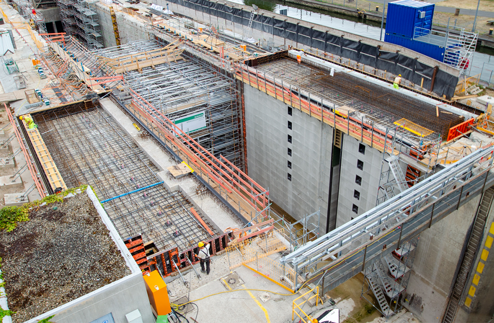
Because of the cramped conditions for the construction site facilities, the lack of space in the lock chamber and the specifications of the building contractor, the experts from PASCHAL developed formwork panels in a combination of LOGO.3 wall formwork and aluminium beams as walers from the GASS program.
One forming and concreting cycle was about 565 m², 21.70 m long and 13 m high and was carried out 5 times per chamber wall.
A "formwork panel" of about 282.5 m² was constructed for each chamber wall. One concreting cycle was needed for the total height and was carried out in parallel, i.e. at both the right and left side of the chamber.
LOGO.3 elements at the top of each formwork panel were equipped with concreting platforms to provide maximum safety for the concrete workers.
In order to make this possible in practice on site, the formwork experts, in coordination with the responsible site manager, developed a horizontally acting spacer from the GASS aluminium shoring system and elements of the PASCHAL TG60 scaffolding. Spindles were provided at both ends to spindle back the formwork panels, to check the offset to the next concreting cycle, and to check and replace the Zemdrain covering as needed.
Millimetre precision and safety at a distance
Seven horizontally acting support units, each consisting of seven horizontal GASS towers with six shafts and spindles on both sides, were used.
The support units were positioned on longitudinal steel beams, which were supported on heavy-duty rollers. The heavy-duty rollers were guided in U-shaped rails, which were aligned in the mortar bed on the ground.
Due to the steel beams under the support units, the entire support structure with the seven support units could be moved to the next concreting cycle in one piece.
The five concreting sections had to comply with the specified tolerance of 5 mm of clearance between the lock chamber walls. This was checked by an external surveyor's office while construction was ongoing.
One forming and concreting cycle was about 2 x 282.5 = 565 m², 21.70 m long and 13 m high and was carried out 5 times per chamber wall.
Over-sized spacers that can be adjusted to the nearest millimetre
The volume of the oversized spacer was around 3,000 m³. Each of the horizontal tower levels was equipped with plywood planking to ensure safe access to the support spindles on the formwork shields. A spacious and safe working platform was provided on the upper level on site, which also served as a concreting level. During the concreting work, concreting took place on alternate sides in order to safely comply with the specified fresh concrete pressure of a maximum of 50 kN/m² and to comply with the narrow tolerance range of just 5 mm with regard to the clear end chamber width dimensions.
50 cm high concrete sections were therefore produced alternately in each section of the lock chamber.
Concreting took place with a concrete as per ZTV-W 219 C20/25 LP, XC4, XF3, XM1, WF. In order to reliably prevent segregation at the fall heights, the mouthpiece of the concrete pump was extended by using screw-on plastic tubes.